Cluster description
A cluster consists of 2 and more nodes, which communicate with each other. A Proxmox cluster allows to manage it using one WebUI, which can be addressed on each node in the cluster.
If you are interested in High Availability the count of nodes should be uneven (3, 5, ...) to avoid problems in case of a cluster network split.
Before starting to create a Proxmox cluster all nodes should be updated to the latest software version.
The Proxmox version installed on the nodes should be the same on all nodes. Please refer the Proxmox documentation how to update all nodes of a cluster.
Node
Landitec GmbH appliances preloaded with Proxmox are available in some models. The following table lists the appliances with some hardware details.
| Model | OS disk | LVM disk | unused disks | Network |
|---|---|---|---|---|
| scope7-5030-Proxmox-M | 1 | 1 | 6 | |
| scope7-5030-Proxmox-L | 1 | 1 | 1 | 6 |
The OS is installed on one disk and the next disk is used as storage for VM images (LVM). All other available disks are not used by default and can be used for own custom storage configurations (e.g. Ceph).
There is no need to use the same appliance models within a cluster. Depending on the requirements different models can be mixed, but the Proxmox software version should be the same on all nodes.

Beside the same version, all nodes should have the same time, so it is recommended to configure setting time via NTP.
Network
Each node must be connected to the same network, from which the Proxmox WebUI can be addressed. An additional connection to another network for dedicated cluster communication is recommended.
Later in this guide this network will be used for Ceph, which requires at least a 10GBit network. For cluster communication a 100MBit network is sufficient.
Changing hostname or IP of a node will not be possible after adding a node to cluster.

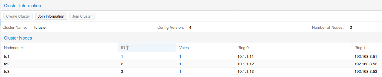
This shows an example of a cluster of three nodes, which are connected over two networks. The network MGMT is for addressing the Proxmox WebUI (Management) and the network CLST is used for the cluster and shared storage. In this guide the cluster networks are configured as in this table listed.
| Node | Ring 0 / MGMT | Ring 1 / CLST |
|---|---|---|
| tc1 | 192.168.3.51 | 10.1.1.11 |
| tc2 | 192.168.3.52 | 10.1.1.12 |
| tc3 | 192.168.3.53 | 10.1.1.13 |
A 2-Node cluster with quorum is built up similar, just one node is replaced by a small server. The only job of this server is to add a vote to the cluster, so if one node is failing the cluster is able to run VMs.

Build the cluster
Build up a cluster starts by accessing the WebUI. In the Datacenter menu is a Cluster menupoint. Here you can find information about an existing cluster or buttons to create a new one.
On the first node a new cluster can be created by clicking on the button Create Cluster. In the appearing dialog insert a name for the new cluster and an IP address, if the hostname cannot be resolved to an IP address of the node. Some seconds after the click on the Create button a new cluster with just one node is created.
To add another node click on the Join information button and inside the dialog on Copy Information. Now the needed information to join another node into the cluster are copied into the clipboard. Optionally the text in the field Join Information can be copied manually. Now open the WebUI of the new node and go to the Cluster menupoint in Datacenter. Open the join dialog by clicking on Join Cluster and paste the copied data into the field Information. Other fields will be filled automatically, but the fields Password and Corosync Ring 0 have to be filled by the user with appropriate values. The button Join starts the process to add the node to the cluster. Perform this for all nodes, which should be added to the cluster.
While joining the cluster the SSL certificate of the WebUI will be changed. Therefore you have to reload the webpage to renew the used SSL certificate of the connection.
All nodes of the cluster are now listed under Datacenter and now all nodes can be managed from each node in the cluster.
Even if it is possible to use different appliances to build a cluster, the VMs always need a uniform view to the node. Otherwise it is not possible to migrate VMs from one node to another. The important requirement are the network settings. If a VM needs access to the bridge vmbr0 and vmbr1, then all nodes where the VM can migrated to must have such configured networks.
Migration from a VM from one node to another also needs free resources for CPU, RAM and Disk on the target node. Without shared storage just an offline migration is possible. The VM has to be stopped and then it is possible to migrate it to another node.
Restore a cluster node
In case of a node failure a replacement node can be created in a few steps using a backup file and SDR. For this copy the backup file, created by the command pxbackup, onto the SDR USB stick (file on stick must be named configuration.dat). Now insert the SDR stick into an USB port of the replacement appliance and power it on. After SDR is finished power off the appliance and remove the SDR stick. Connect all network cables as before at the original appliance and boot the system. The node will reboot to activate the configuration from the backup file and shortly it will join the existing cluster.
If another appliance model is used as replacement, then the naming of networkports can differ. In this case login using monitor and keyboard and adjust the networkports in the file /etc/network/interfaces. After it reboot the node.
After the node is back into the cluster a software upgrade to the latest version is recommended.
Disks cannot be reconfigured by the restore process. Please reconfigure your disks manually (like LVMs, ZFS, Ceph OSDs, etc...).